Sunlight Detecting Flowerpot
A helpful/useless robot that helps your plants chase the light.
Interaction Highlights
INTRODUCTION
As part of my Physical Computing project, I set out to create a helpful or not helpful device that changes how I interact with an everyday task.
The result is a Sunlight-Detecting Flowerpot Platform that automatically adjusts and maintains its position when I am uncertain about the most suitable spot on my windowsill for optimal plant growth.
Inspiration
Brainstorming
Initial Design:
A bottom disc driven by a motor controls the orientation of the flower pot.
A second motor above the rotatable disc adjusts the tilt angle of the flower pot.
A fixture at the top securely holds the flower pot in place.
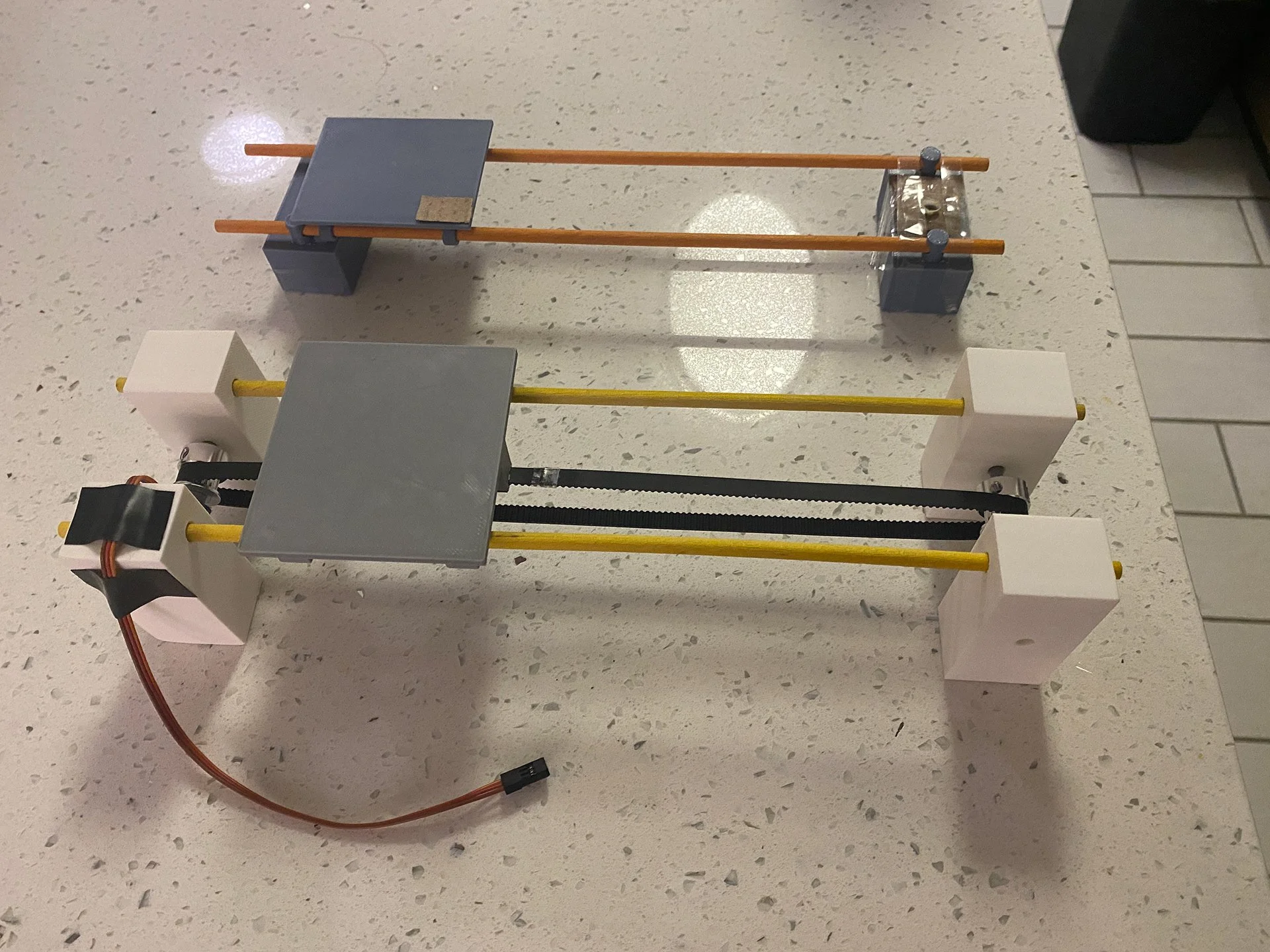
Improved Design:
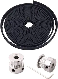
Uses a linear belt drive to move the flower pot.
A motor on one side drives gears that move the belt, shifting the flower pot along the platform.
A bracket on the platform supports a photocell positioned next to the flower pot to detect sunlight intensity.
When the sunlight intensity reaches a specified value, the motor stops, and the linear belt maintains the platform at its current position.
Concept Sketch
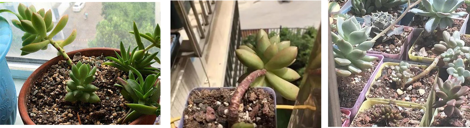
Succulent plants do not require very regular watering, but they have strict requirements for lighting conditions. Inadequate sunlight can cause succulent leaves to grow excessively. On the other hand, excessive sunlight can lead to the loss of moisture and cause sunburn.
There are many smart watering pots on the market, but few pots can adjust the sunlight environment to meet the needs of succulents. Therefore, I want to attempt a proof of concept by using Circuit Playground Express, photocell, 3D printed parts, motors, linear belts, and gear sets to complete this device.
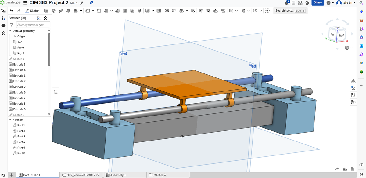
Fabrication
Step 1: Measured the dimensions needed to fit the motors and other components.
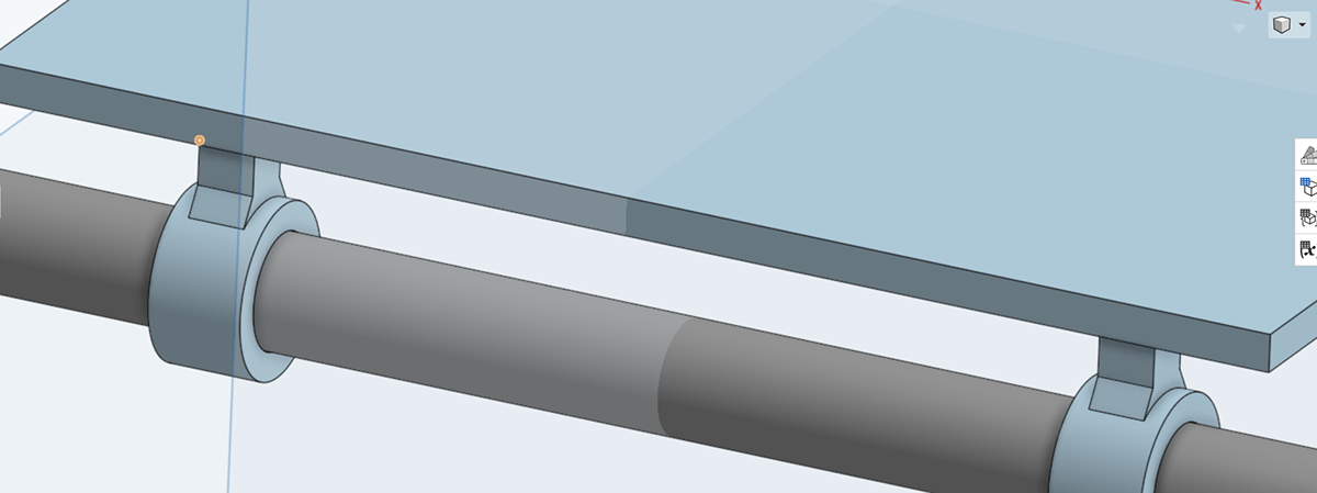
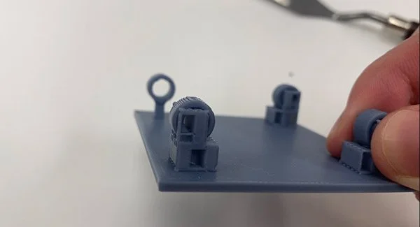
Step 2: Drafted 3D models using Onshape, including a movable platform, two bases to hold the motors.
Following advice from my professor, I added fillets to the support columns between the platform and the cylindrical rails to increase the strength of the components.
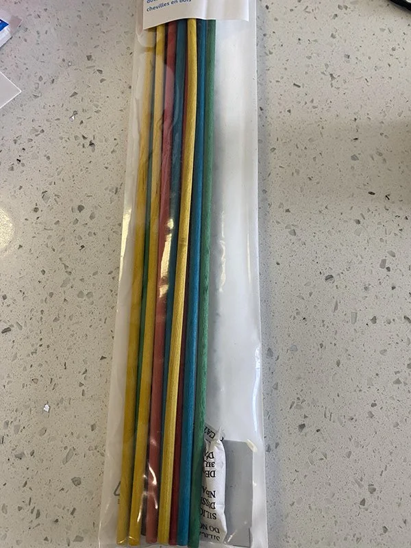
Additionally, anticipating that 3D-printed rails might not be smooth enough due to additional support during printing, I purchased 3/16-inch wooden rods. Also, I purchased a linear belt and gear set through online shopping.
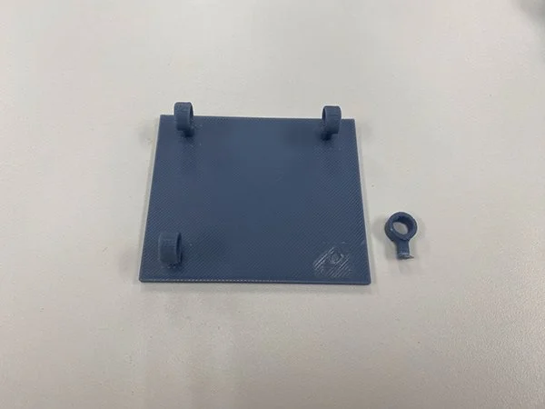
Platform
Breadboard/CPX/LED
Assembly
End bracket
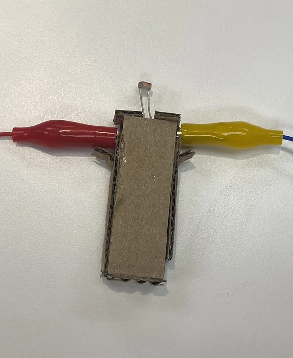
Photocell
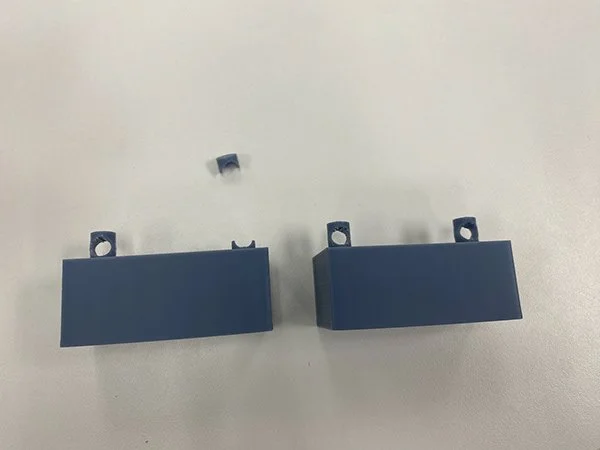
During assembly, two components broke, which I salvaged using superglue.
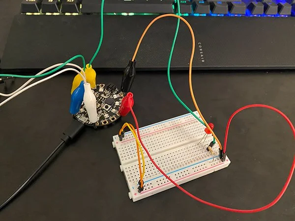
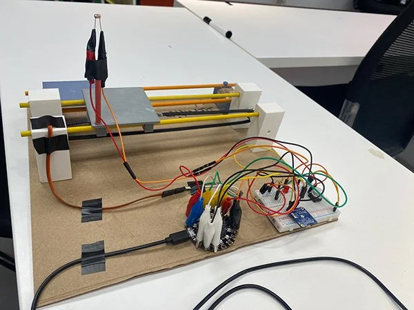
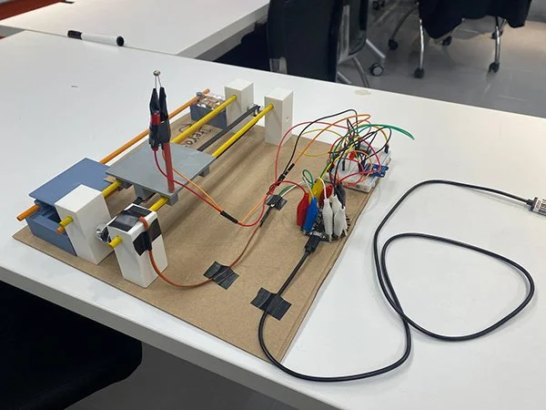
The remaining components were connected on a breadboard.
An LED indicator was added, improving debugging efficiency.
The photocell was connected using alligator clips.
The device was secured onto a cardboard base.
Areas for Improvement:
While all major functions are working as intended, there are many issues:
Bulky photocell support
Fragile 3D-printed parts
Belt misalignment
The assembly relied heavily on cardboard and tape.
Iteration 1
Iteration 2
Improvements Made to 3D Printed Parts
Improvements in Iteration 2:
Better belt and gear alignment
Smoother motor operation
Slimmer photocell support with wooden rod
Larger flowerpot platform
Redesigned motor bearings
Added Mode 3 for automatic sunlight tracking
Mode
Mode 0: Standby mode.
Mode 1: Testing mode, used to check the interaction between the linear belt and the gears.
Mode 2: Detection mode. Upon button press, the platform checks sunlight intensity at the extremes. If sufficient light is detected, the platform stops, signaling completion with a red LED. If light is insufficient, the platform moves left and right three times before returning.
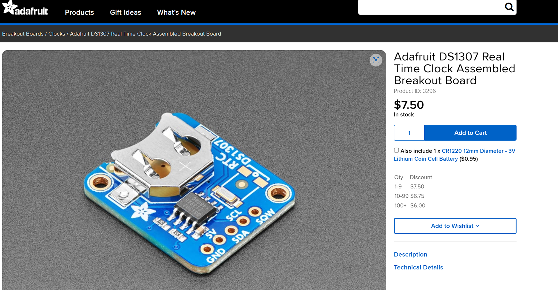
Mode 3: Sunlight Tracking Mode. Tracks sunlight using RTC DS1307 (Real Time Clock) Between 7:00 and 18:59, the platform follows sunlight. From 19:00 to 6:59, it ONLY displays current time. When reaching the limit while tracking, the platform resets to its initial position.
Reset Button: To prevent jamming, a reset feature is implemented.
Advanced Components
DS1307 is a great battery-backed real time clock (RTC) that allows microcontroller project to keep track of time even if it is reprogrammed, or if the power is lost.
Final Assembly
Bad Example of Support Planning
Challenges and Lessons Learned
This project taught me CAD modeling with parametric design and broadened my understanding of how it differs from polygon modeling software.
I got used to using a caliper and leaving proper allowances for tolerance, and I learned how to plan the placement of 3D printing supports to prevent damage when removing parts. I also learned the importance of careful circuit layout to prevent short circuits.
In addition, this project helped me gain a deeper understanding of the possibilities of the Adafruit Circuit Playground Express. Many features, such as audio output, lighting effects, motion sensors, and capacitive touch, were not used in this iteration, but I hope to keep explore and apply them in my future projects.